
Now that you have received your CH400 CloudHawk hardware tracking units, please review the following document which provides tips and best practices on installing your devices.
The following details will help ensure that you get the best performance from the hardware.
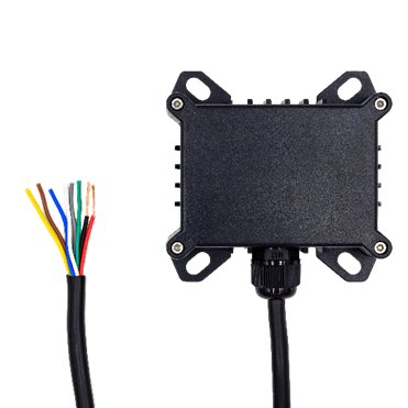
About the CH400 CloudHawk Tracking Hardware
The following instructions are for installing the CH400 CloudHawk Tracker. The CH400 supports both wired and wireless BLE sensors. The CH400 is also capable of reporting engine run-time by connecting to a battery or alternator as well as monitoring PTOs.
Things to Know Before You Get Started
- The CH400 hardware shipped to you has already been added to your Account.
- For the target vehicle/asset, plan on connecting the CH400 unit to a constant power source. Devices are typically delivered with a battery charge level between 60-100% capacity. If the battery is drained, connect the CloudHawk hardware to a 8 ~ 40V power source (red = Positive; Black = Negative) and it will come online within a few minutes.
- During installation, the installer can confirm that the GPS signal level is adequate, especially if hiding the tracker. Instructions below are included on how to complete this test.
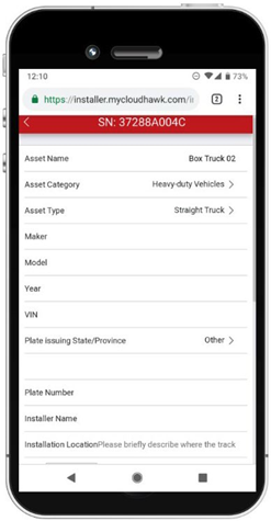
How to Access the Installer Portal
CloudHawk has a specifically designed installer portal for designated installers. This portal is completely mobile-friendly and allows installers to view information pertinent to hardware health and setup.
You can access the installer portal at: https://installer.mycloudhawk.com
Login credentials will be sent by your admin before installs begin. Alternatively, you may receive an email with individual links to each asset. In this case, no login is required, and you may skip the first 3 steps below after clicking the link for the serial number (SN) you are installing.
If you're an Admin user and need to provide an installer with access to the Installer Portal, see Adding New Users to Your CloudHawk Portal and select the Installer role.
If you'd prefer to send temporary links, see Share Temporary Installer Portal Links
- Login to the installer portal using
- Scroll or search for the SN of the unit being installed.
- Click on the SN to access the configuration page for that unit.
- From the configuration page, you can check GPS and Cellular signal levels to confirm the install location will work.
- Clicking on the “Asset Name” field will bring you the asset information page, here you can fill in the asset name and other identifiers.
Installation Steps
Please note that the device's lithium rechargeable battery performs best in temperatures ranging between -10°C and 45°C. Exposure to temperatures above 60°C could permanently damage the battery, impacting the device's performance. Furthermore, in temperatures of -20°C or lower, the device will switch to relying solely on external power. Therefore, it is essential to select a location for installation that stays within these temperature ranges to ensure optimal operation and longevity of the device. The internal temperature is also reported in the Installer Portal to help with tracker placement.
- Select a location for installation that supports access to constant electrical power.
- Place the CloudHawk tracker in the location you intend to install it.
- If you are hiding the tracker in a new location where you have not tested the GPS signal level, you can verify that the location supports an adequate GPS signal level which ensures that it will continue to track. Using the installer portal, confirm the GPS signal strength is greater than 29. It is recommended to take the asset for a short trip of at least 1-2km and confirm the GPS signal level while in transit.
- Connect the CH400 unit to a constant power source.
- Red – Positive (8 ~ 40V)
- Black – Negative
- The CH400 red and black wires should be connected directly to a 8 ~ 40V circuit with constant (not ignition-only) power. Install a 3 Amp in-line fuse on the red wire.
- Use a solder or crimp terminals to connect the wires.
- Use anti-corrosion grease and shrink tubes with internal adhesive on all connections and unused sensor wires.
CH400 Colour Wiring Reference
|
Wire Colour |
Purpose |
|
Red |
Positive (8 ~ 40V) |
|
Black |
Negative |
|
Yellow, Blue, Green |
Temperature Sensor(s) |
|
Brown |
Ignition Detect |
|
White |
PTO / Door Sensor |
|
Grey |
Sensor Ground |
Connecting Wired Sensors
The first installation step is to configure the sensor in the installer portal:
- Click “Add new sensor” at the bottom of the configuration page
- Select the type of sensor you are installing, and the portal will automatically select the appropriate color wire for you on the next row.
- If there are multiple wire options, click to see a list of color options. Select one of the colors and proceed to connect one of the two sensor wires to that wire on the tracker.
- If applicable, fill in the “Location” field. For example, “Front” or “Trailer Door”
- Click “Save”.
Connecting Wireless Sensors
The first installation step is to configure the sensor in the installer portal:
- Click “Add new sensor” at the bottom of the configuration page
- Select the type of sensor you are installing. Be sure the select the “Wireless” version for sensors that have both wired and wireless variants.
- Click on the Sensor ID field and select the sensor you are installing. You will find this ID on a white label on the physical sensor. If you have a large number of sensors available in your account, you can use your browser’s Find function (usually Ctrl+F) to locate the correct ID.
- Fill in the “Name” field. Typically, customers use the location of the sensor as the name. For example, “Front” or “Trailer Door”
- Click “Save”.
Wired Sensor Installation Steps
Wired Temperature Sensors
The following components are needed to install the wired temperature sensors
- 22 AWG gauge wiring
- Use a solder or crimp terminals to connect the wires
- Apply anti-corrosion grease to the exposed wiring
- Apply a shrink tube with internal adhesive
- The supplied sensor has two wires 12” long. Connect one wire to the sensor input wire you selected in the installer portal and the second to the grey wire of the CloudHawk Tracker
- Additional wiring not included.
Ignition Detection
- This input detects if the vehicle engine is running. Once connected, it automatically updates the engine hour field in the CloudHawk portal.
- Connect the brown wire of the CloudHawk Tracker to a vehicle power source that is only powered while the ignition is on.
- A secondary function of the ignition detect line is to track reefer engine run time. Please refer to Appendix A for the detailed installation procedure.
PTO Sensor
- Connect the white wire to the spade terminal on the indicator switch mounted to the PTO.
- Connect the grey wire on the tracker to good ground.
- If the PTO is mounted on a vehicle, be sure that the engine is stopped, and the vehicle is safely immobilized to prevent any movement.
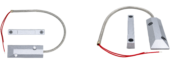
Wired Door Sensors
The following components are needed to install the wired temperature sensors.
- 22 AWG gauge wiring
- Use a solder or crimp terminals to connect the wires
- Apply anti-corrosion grease to the exposed wiring
- Apply a shrink tube with internal adhesive
- The supplied sensor has two wires 12” long. Connect one to the white wire and the second to the grey wire of the CloudHawk tracker
- Additional wiring not included.
- See the image below for install positioning. Ideally have the two parts ½” apart from each other which is a closed circuit (closed door). If the two magnetic parts separate by ~1.5” the sensor will signal that it is open.
Appendix A: Reefer Engine Run Time Tracking
- Alternator output can be used to monitor engine run time. CloudHawk CH400 device is equipped with the necessary hardware circuitry that allows installation to the 12V-DC Alternator output.
- Installers should locate the 12VDC output terminal of the alternator. In some models of alternators, some outputs are not regulated DC, for example, the W terminal in a certain model indicates the wave output of the alternator. These outputs are usually pulsating outputs and cannot be used with CH400, only 12V to 16V-DC can be used for this purpose.
- In some models this terminal can be connected to the reefer’s existing wiring system, in which case a new splice point should be created so the line is branched and connected to the brown wire in the CH400 device.
- In alternative models, this terminal is left floating, in which case the brown wire can be connected directly to the alternator output terminal.
- In all engine run time tracking installations, the charging voltage for the CH400 device must be the reefer’s internal 12V battery, to allow reliable operation even when the reefer is in standalone mode (without the tractor). In this case, a 3 Amp fuse must be used between the battery and the charging input of the CH400 device. The ideal location of the fuse is as close as possible to the reefer battery.